- Get link
- X
- Other Apps
The equations for noise margins are provided below use the minimum of maximum numbers as described above. In other words noise margin is a measure of the immunity of a gate from reading an input logic level incorrectly.

Logic Families Bipolar Logic And Unipolar Logic Families

Logic Families Digital Electronics

Diode Transistor Logic Dtl
Noise immunity of cmos gates is equal to v dd.

Diode transistor logic noise margin. A noise margin introduction of digital logic families miniature low cost electronics circuits whose components are fabricated on a single continuous piece of semiconductor material to perform a high level. N if any input goes low the base current is diverted out through the input diode. Rtl was made from discrete transistors and resistors and manufactured on printed circuit boards with several gates per board.
In a dtl circuit the collector output of the driving transistor is separated from the base resistor of the driven transistor by several diodes. Improved gate with reversed diodes. These boards were plugged into board sockets with.
Minus the maximum low level voltage which may be seen at the receiver ic. In general ttl and ttl compatible circuits tend to. Noise immunity of a ttl gate represents its ability to withstand the interference of noise in its smooth operation.
For a valid logic low the worst case noise margin for the circuit is the maximum low level voltage which may be output from the driver. Diode transistor logic 1 chapter 5 diode transistor logic resistor transistor logic was an early form of logic used in the 1950s and early 1960s. Hence noise margin is the measure of the sensitivity of a gate to noise and expressed by nml noise margin low and nmh noise margin high.
In digital integrated circuits to minimize the noise it is necessary to keep 0 and 1 intervals broader. The noise margin of a logic level is defined as the voltage gap between the maximum low voltage of high input vil max and maximum voltage of the low input vil min of a logic gate. Noise margins of ttl gates were found to be equal to 04 volt.
The noise margin is also defined as the amount by which the voltage signal exceeds the threshold level for the exact high or exact low. The transistor cuts off and v out goes high. N the gate works marginally because v d v bea 07v.
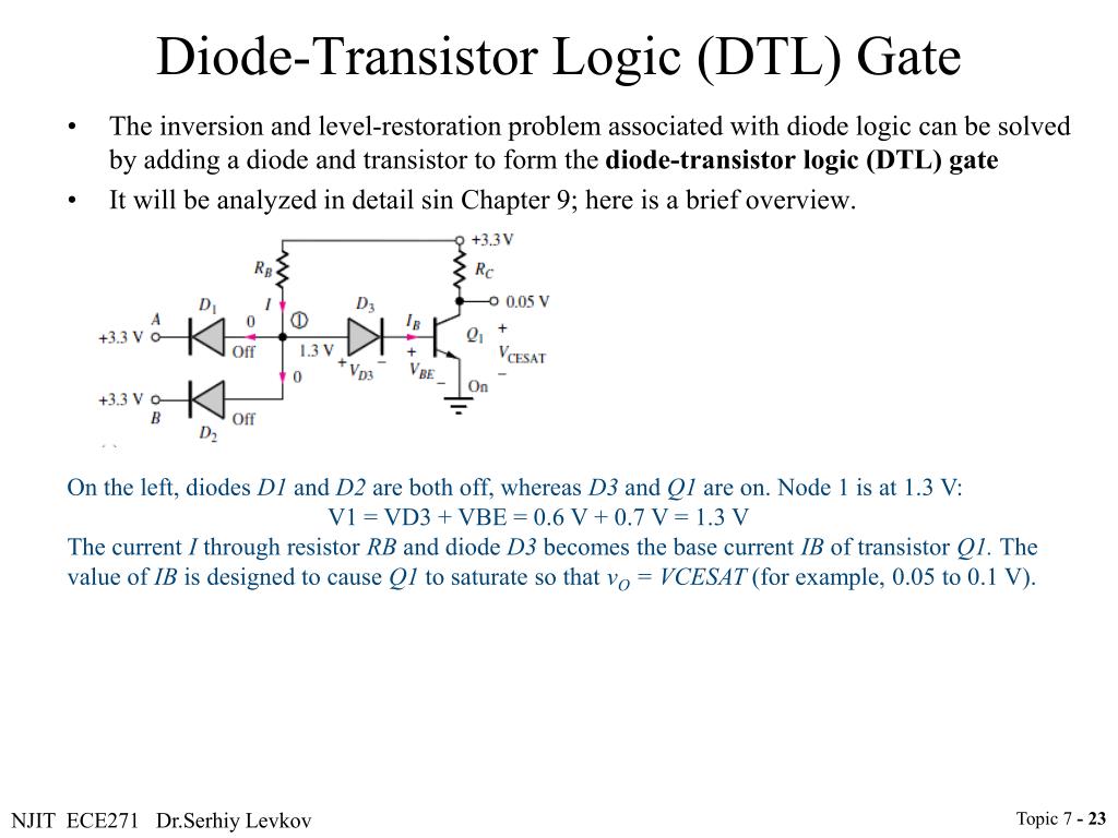
University of connecticut 60 diode transistor logic dtl n if all inputs are high the transistor saturates and v out goes low. We then say that these gates are immune to noise up to 04 v. In the low state however v ilmax exceeds v olmax by only 03 v so the dc noise margin in the low state is only 03 v.
Nml and nmh are defined as nmlvil vol and nmh voh vih. That is it takes at least 07 v of noise to corrupt a worst case high output into a voltage that is not guaranteed to be recognizable as a high input. N this is a nand gate.
Ihmin by 07 v so ttl has a dc noise margin of 07 v in the high state. This is a term derived from the theory of noise voltages. Diode transistor logic in dtl diode transistor logic all the logic is implemented using diodes and transistors.
Diodetransistor logic dtl is a class of digital circuits that is the direct ancestor of transistortransistor logicit is called so because the logic gating function eg and is performed by a diode network and the amplifying function is performed by a transistor in contrast with rtl and ttl.

Lessons In Electric Circuits Volume Iv Digital Chapter 3

Logic Family

Transistor Transistor Logic

Introduction To Logic Gates Not And Nand Or Nor

Transistor Transistor Logic

Sgt Inverter Performance Gain And Noise Margin A

Introduction To Digital Logic Families Guruji Notes

Understanding Digital Logic Ics Part 2 Nuts Volts Magazine

Diode Transistor Logic Dtl

Ppt Topic 7 Digital Circuits Intro To Digital Electronics

3 4 Bipolar Logic 1 Diode Logic Ppt Video Online Download

Analytical Review Of Noise Margin In Mvl Clarification Of A
- Get link
- X
- Other Apps
Comments
Post a Comment